| MGF Cars: Hydragas Sphere Nitrogen Recharge |
| Update April 2022: Whilst our attempts at repairing the Hydragas spheres below were not successful, the reconditioned units provided by Hydragas and Hydrolastic Service Ltd. most certainly are and we highly recommend them. We purchased a set through Rimmer Bros. and for overseas MGF owners this may be the most cost effective method where freight is concerned. |
When introduced twenty years ago, pundits praised the new MGF for the exceptional ride and handling that such a small car provided.
Whilst not a new concept, the hydragas suspension system fitted to the MGF represented the ultimate development of Dr. Alex Moulton's original design concept; comprising front to rear, interconnected nitrogen gas over liquid "springs".
However, with the passage of time the system loses effectiveness and the situation is exacerbated by two main factors: First, the hydragas spheres themselves were not designed with future maintenance in mind. Granted, space constraints would not have made this easy, but it is somewhat odd that the otherwise brilliant Dr. Moulton did not design the sphere so that it could be rebuilt with new seals etc.
Second, to make matters worse, some moron at Dunlop, the manufacturer of the hydragas spheres, decided to scrap the tooling several years ago rather than turning it over to British Motor Heritage as should be done with all classic car tooling once British manufacturers no longer deem it current.
Fortunately, the quality of components inside the spheres appears to be relatively good, so for those MGF owners who do not relish the prospect of taking the somewhat retrograde step of replacing their hydragas system with the "spring in a coffee can" kit offered as an alternative, it should be possible to squeeze a bit more life out of existing hydragas components.
Aside from the occasional lower seal rupture causing loss of fluid, the main issue as the years pass seems to be that the car gradually loses ride height. The usual reaction to this is to say: "the suspension needs pumping up". Well, it does, but not in the way that most people think. Simply putting in more fluid will restore the height but is a classic case of treating the symptom, rather than the cause.
What is really happening is that the nitrogen charge in the upper chamber is ever so slowly becoming depleted. Sure, putting in more fluid will compensate but suspension travel will be reduced and ultimately eliminated, giving a rock hard ride and usually ruining the rubber membrane separating the fluid & gas in the upper chamber, rendering the sphere scrap.
The proper fix is to restore the nitrogen charge, however that is a little easier said than done, since no provision to do so was incorporated into the design of the sphere.
|
|
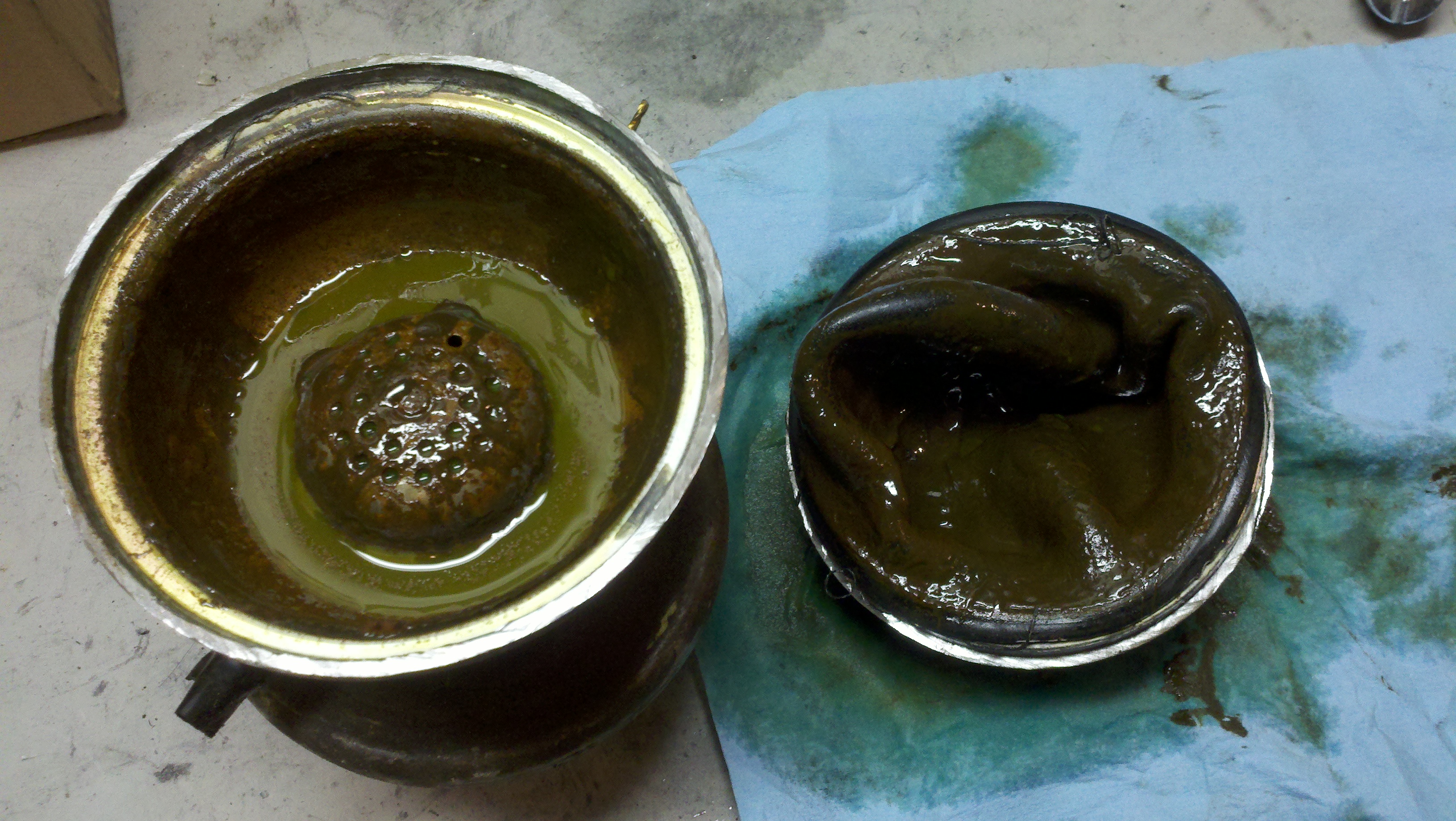 |
This cut open sphere is a classic case of continuing to pump fluid into the system. The car had rock solid suspension and the upper rubber diaphragm had ruptured. This rear unit is now scrap which is a pity since even used rear spheres are becoming somewhat scarce. Limited NOS stocks of front displacers do seem to still be available. |
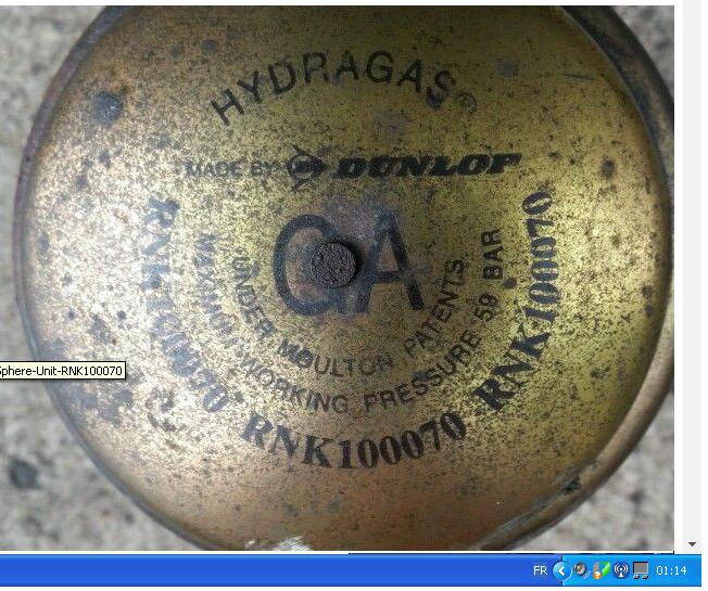 |
Here is the top of a front sphere. Whilst the initial nitrogen charge is only 16.55 Bar (approx. 200 psi), with a fluid charge of around 400 psi, working pressures in the system when the suspension is compressed can reach as high as 800 psi! To refill the nitrogen it will be necessary to modify the sphere & install a 'Schrader' type valve. Schrader, despite several inquiries did not bother to suggest which of their products would be most suited to this task. |
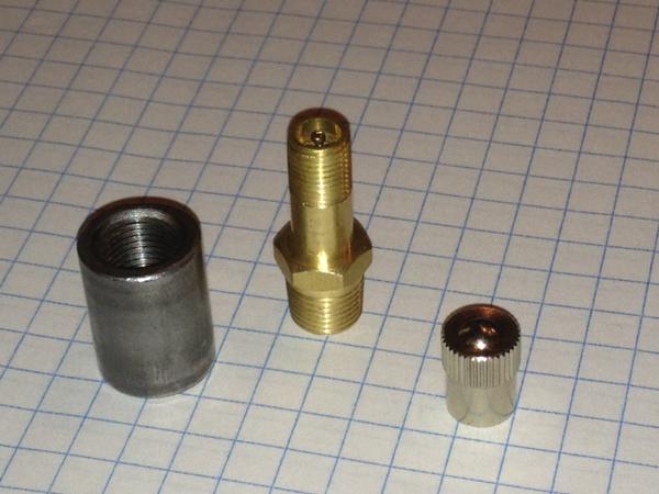 |
An example of the fittings that will be required for each sphere. This weld-in bung is a little tall - we were able to find some lower profile ones (in steel, most are aluminium) with a 10mm height. The bung needs to have a 1/8 NPT internal diameter since most valves are 1/8 NPT O.D. For the valves, I recommend www.schmidtyracing.com. Very helpful folks who sell low profile valves and high pressure cores. |
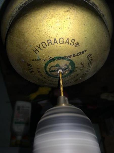 |
On the front, the sphere can be drilled top centre since an access hole will have to be cut in the inner fender regardless. The potential of a leak through the original fill rivet is eliminated into the bargain.
One should hear a whoosh of escaping gas once the drill goes through and no liquid should come out. The presence of the latter renders the sphere scrap. Escaping gas should help to prevent swarf from entering the chamber but it will likely be necessary to shake the unit to get the rest of the rivet out.
|
 |
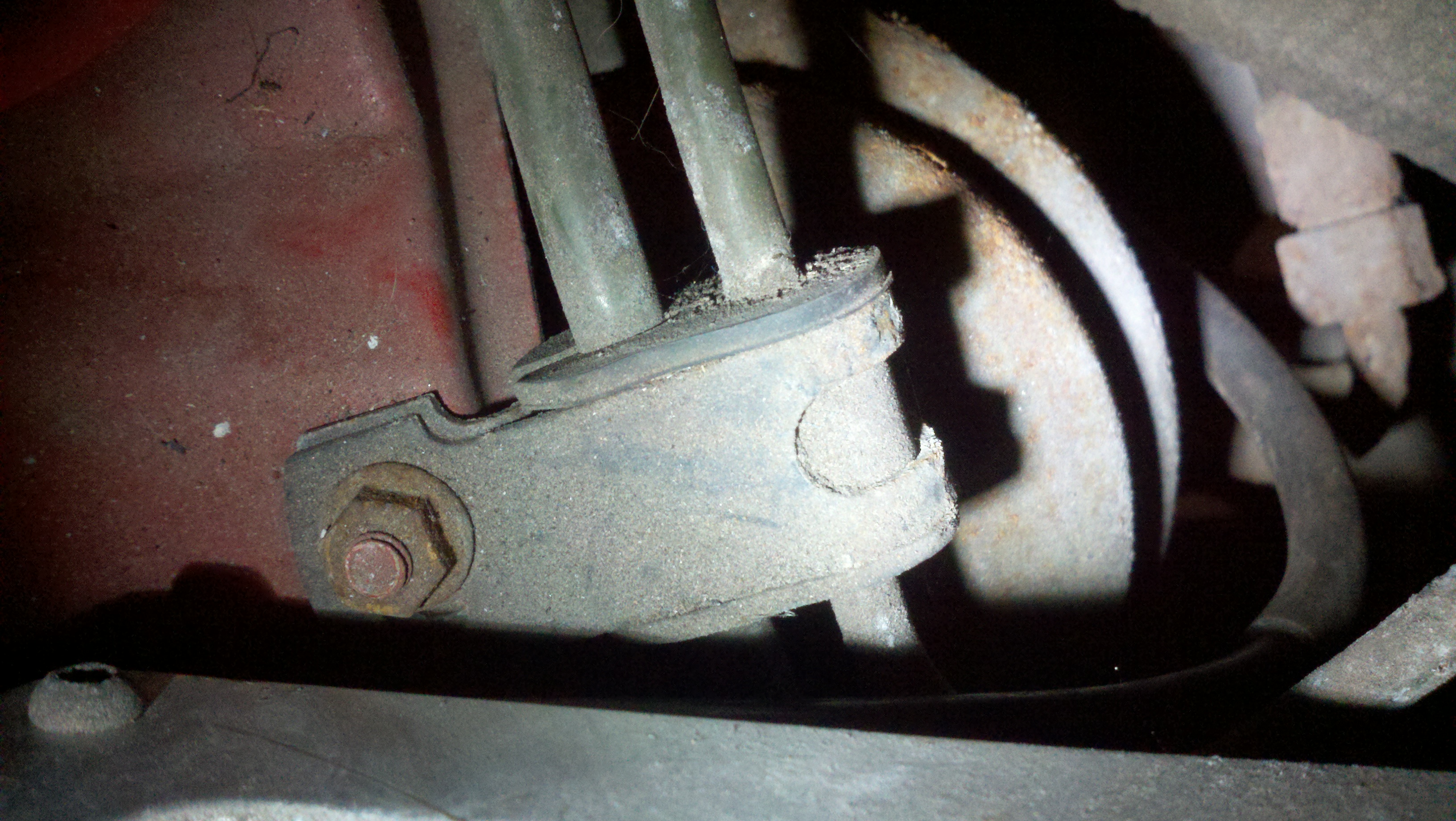
Aside from the lack of a nitrogen charge port in the original design, on the MGF there is very little, if any, clearance above the fitted spheres. At the front, it will be necessary to make minor modifications to the inner fender panel. However, at least the valve can be located in the top centre of the sphere. |
 |
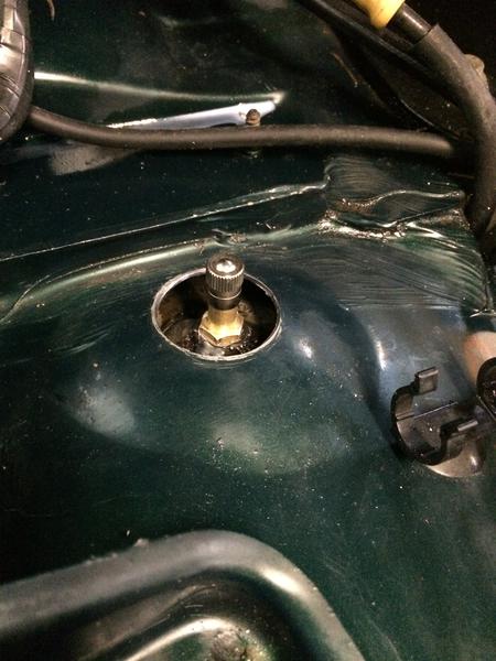
The rear is not much better. This photo shows the left side where there is virtually no clearance between these fuel pipes and the top of the sphere. The right side is a bit better, but the body structure still precludes top centre valve placement . |
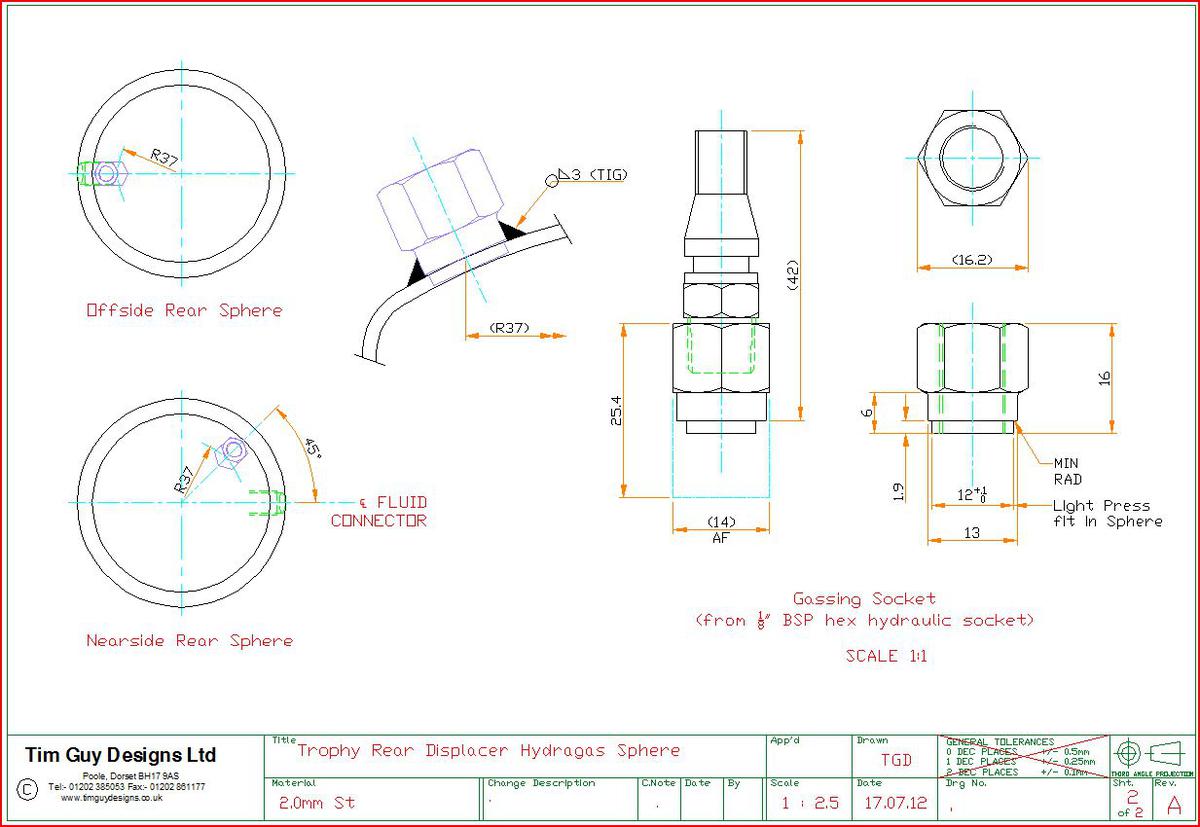 |
On the right rear (UK offside), the nipple can be aligned with the liquid line port, however this drawing advocates positioning the left gas nipple (UK nearside) 45 degrees anti clockwise to the fluid port. We are hoping to avoid this as that would make modified rear spheres handed which is obviously not desirable. |
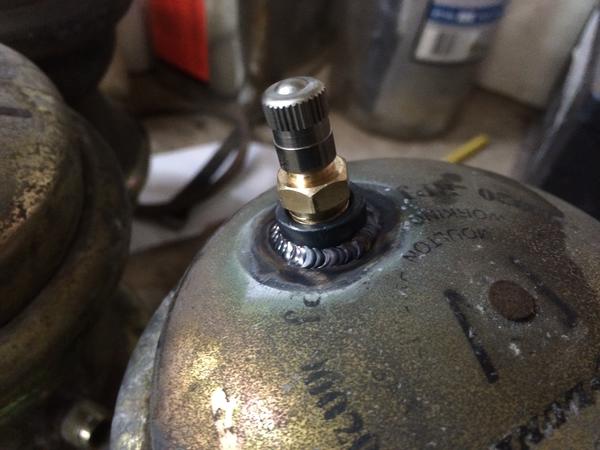 |
The rear gas valve fitted at an angle. This is giving our welder fits owing to the closer proximity to internal rubber components. It also leaves the original nitrogen fill point as a potential source of leakage in which case some advocate welding a small blanking plate over the rivet. |
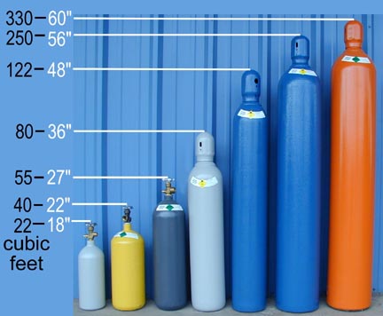 |
Once the gas valves are installed in the spheres, one is going to need some nitrogen. Given the capacity of each sphere is only 491cm3 (0.017410ftł) a 40 cu ft cylinder (approx.$150) should be plenty! The factory gas was 99% nitrogen, 1% SF6 but such a mixture will typically not be readily available from local gas suppliers. |
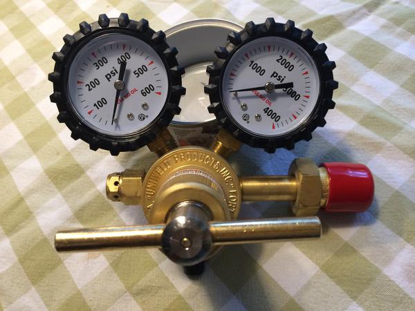 |
A regulator & gauge assembly will be needed to dispense the nitrogen from the cylinder. One gauge shows the pressure in the cylinder, the other the output pressure. Again, I would recommend talking to Evan at Schmidty Racing. |
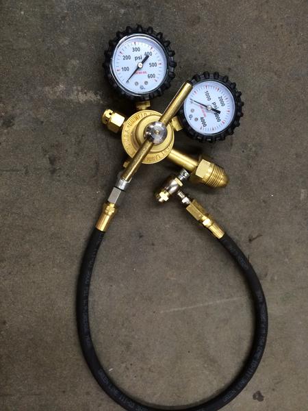 |
This setup would be the minimum requirement for filling the spheres. The fitting at the end of the hose is the 'no loss' type. Those who have a Liquid Levers type tool for filling the liquid side of the system will recognize it. |
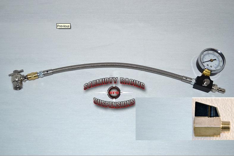 |
However, at Schmidty's site one can build a custom hose assembly and I plan to add a line guage, bleed off and shut off valve. This would allow the fill hose to function as a pressure checking device as well. |
| so that is the theory, now in practice... |
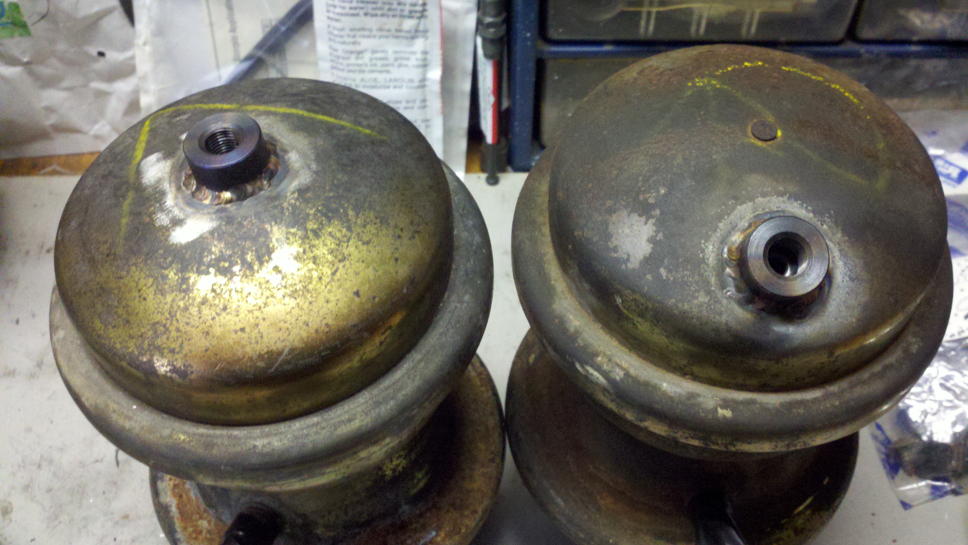 |
The first two spheres deemed usable are back from the welding shop. Unfortunately, when the valves arrived it was discovered that they only screw into the bungs one way, which is not apparent to the naked eye. |
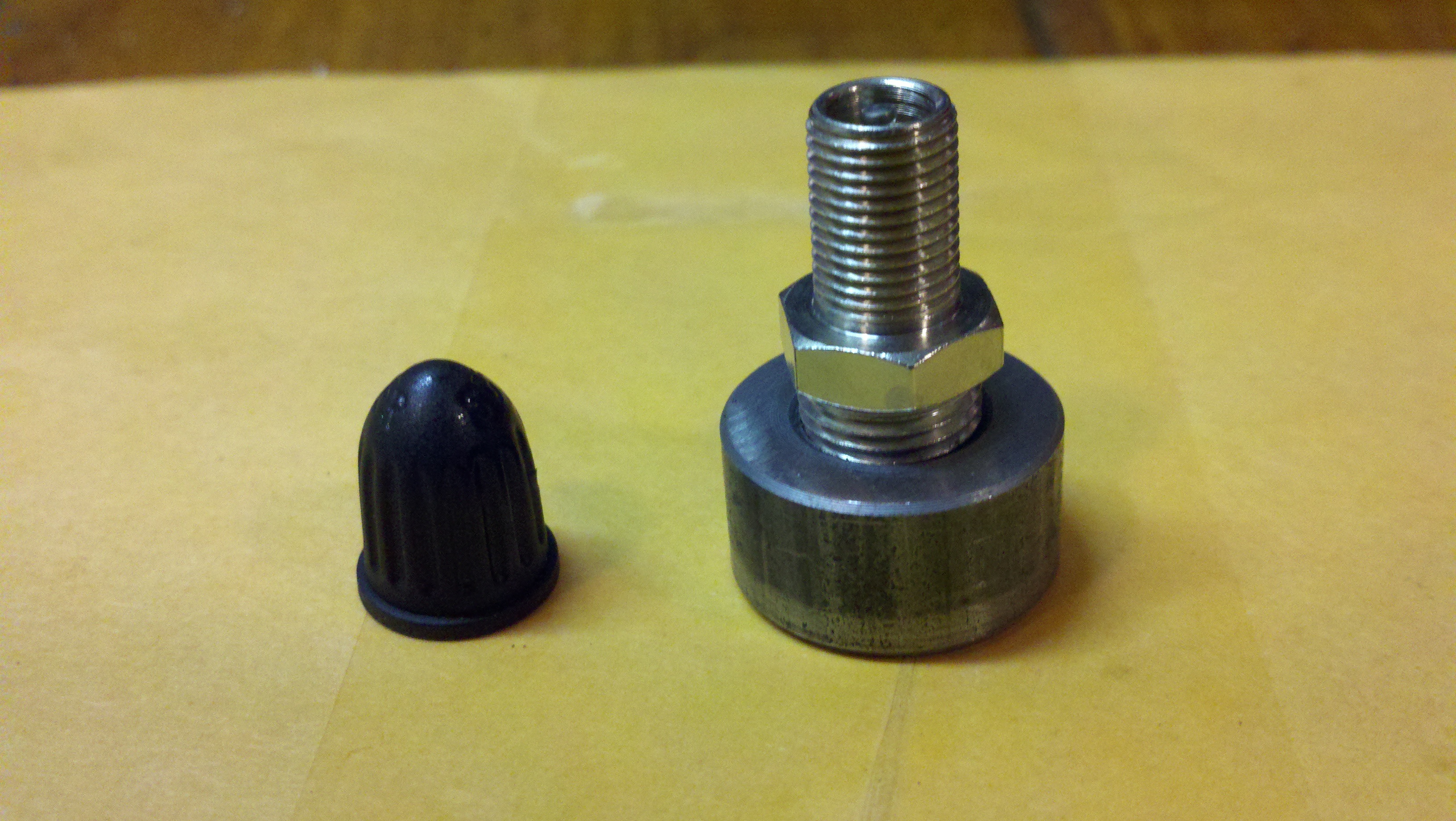 |
Valve and bung assembly. |
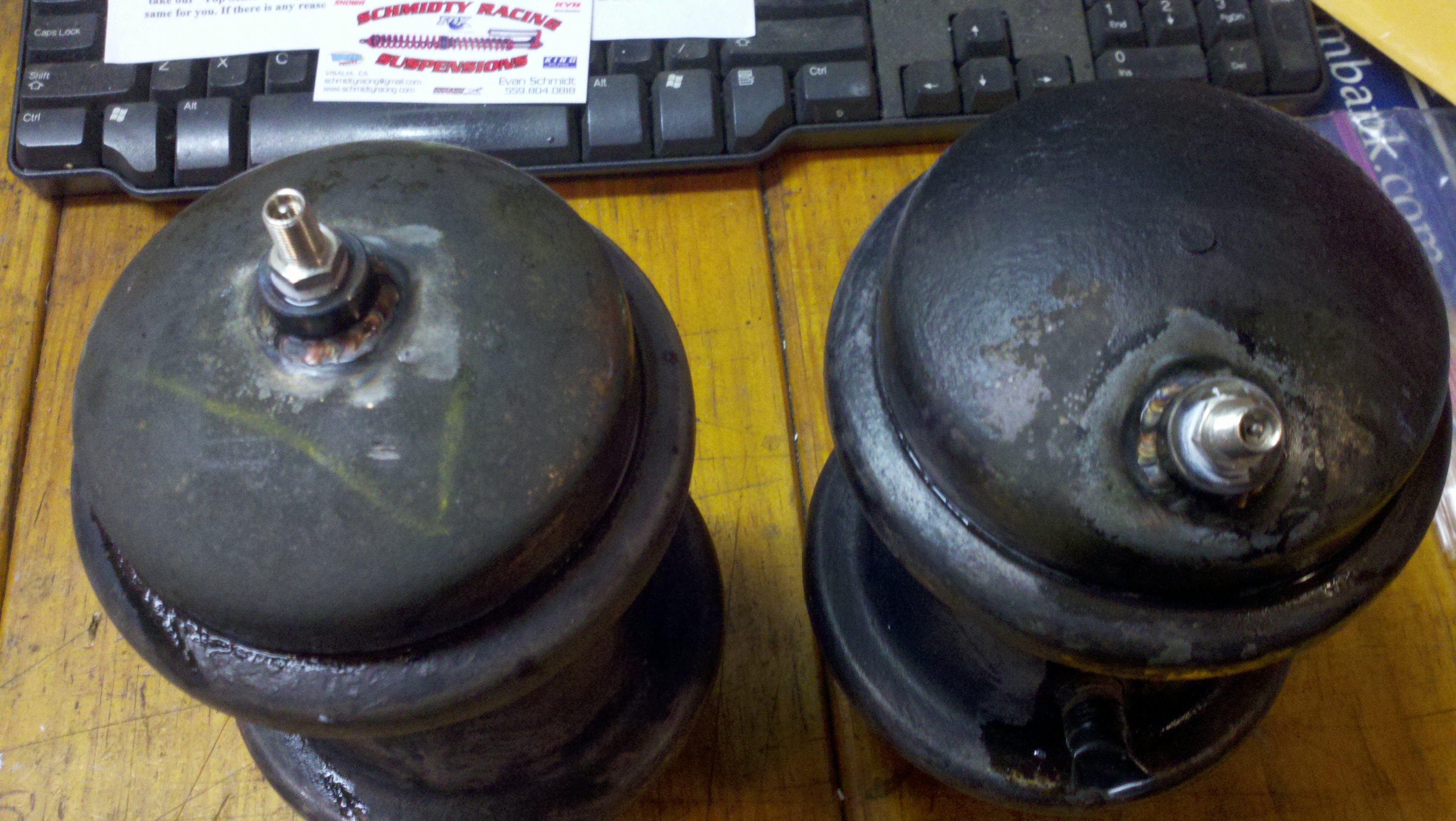 |
Valves fitted and filled with shop air (~95psi) to test for leakdown. We are detecting about 5psi leakdown over a 24 hour period, thus will attempt to correct with some form of tyre sealant product. |
| more to follow! |
As mentioned above, production of Hydragas spheres has ceased so as units fail internally
replacements will become increasingly scarce. Reproducing the spheres would require a massive investment in new tooling.
We approached one stamping firm to get an idea of costs but interestingly their response was that they did not think the
spheres were a stamping application. Rather, they suggested that they were probably produced by 'metal spinning'.
An interim approach may be to modify the spheres to allow rebuilding. If the top and bottom flage areas could be
cut open and have some sort of threaded rings fitted, that might allow seal renewal? |
|
|
| Parts List |
| 1/8 NPT weld-in bung |
GFS CNC Components |
| 1/8 NPT fill valve assy |
Schmidty Racing |
| 800 psi valve cores |
Schmidty Racing |
| regulator & hose assy |
Schmidty Racing |
| nitrogen tank |
local welding supply house |