Home Page
What's New?
C
O
L
O
U
R
Wiring Diagrams
TR7, TR8, SD1
Parts Remanufacturing Projects
TR8 Fuel Injection Conversion
TR7 Rover V8 Conversion
Technical Tips Database
Wedgeparts
Fleet
Books & Links
Policies & Procedures
|
Triumph TR8 GM throttle body fuel injection (TBI) conversion
| Wiring Harness, Electronic Control Module (ECM), ALDL, Check Engine Light |
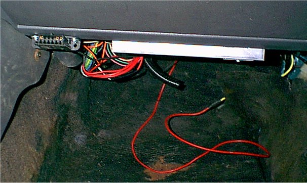
We decided to mount the electronic control module below the glovebox as was factory practice.
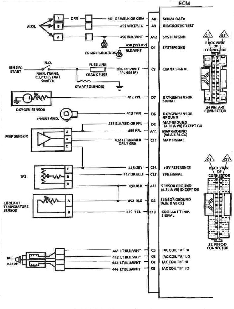
- Wiring Harness: There are two routes to go here: either build a new harness from scratch or modify a factory harness. I prefer the latter approach because GM fuel injection harnesses almost always use the same colour coding which greatly simplifies matters. Furthermore, if one is buying a TBI and ECM from a salvage yard the harness can often be had for little or no extra cost! I like the harness from the Astro vans because it is almost exactly the right length; requires minimal additional wiring to be added and many of the existing component connectors do not need to be disturbed. When removing the harness, don't forget to get the ALDL diagnostic connector from under the dash on the drivers side!
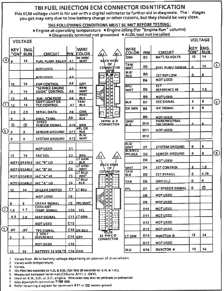
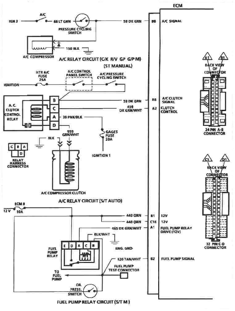
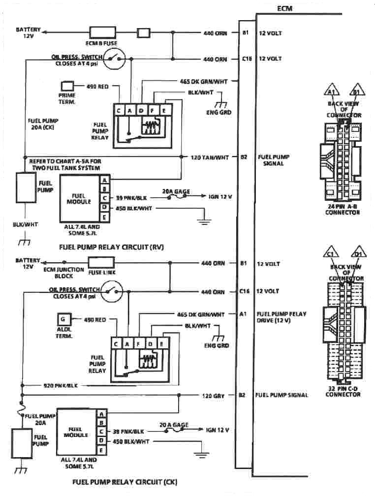
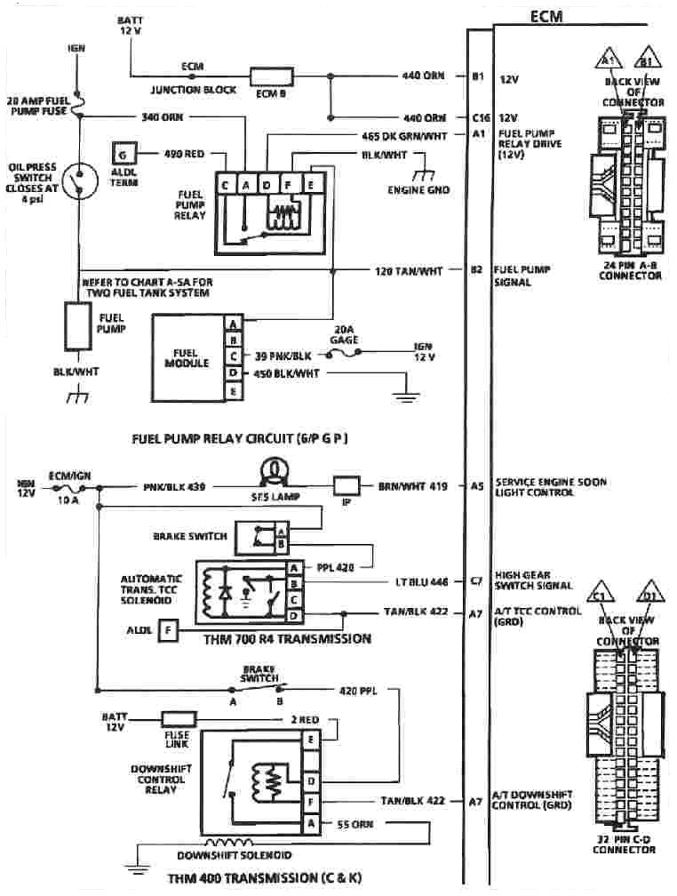
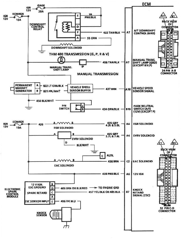
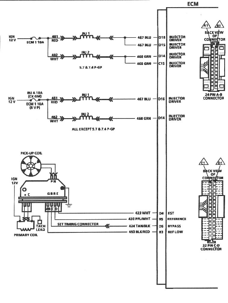
Adapting the harness to your TR8 is fairly easy. The first step is to print out the following seven wiring diagrams. I don't see the need to go through each circuit in detail - if you have a specific question then please email me and I will try to help. However there are some issues that should be addressed: First, the diagrams show a number of different fuel pump circuits specific to GM car lines. The best one to choose for our purposes is the S/T truck layout at the bottom of page two. Second it should be noted that there will be extraneous wires in almost any harness that you get. For example if you don't have a/c on your car then the wires associated with pins A2 and B8 will obviously not be relevant, although I would recommend leaving these wires in place and just coiling them up neatly somewhere in the harness in case you decide you need them at a later date.
1227747 ECM page 1
1227747 ECM page 2
1227747 ECM page 3
1227747 ECM page 4
1227747 ECM page 5
1227747 ECM page 6
1227747 ECM page 7
The most significant modification I had to make to the harness on our green TR7 V8 was to add two relays and the associated wiring to tie them into the vehicle harness. The first relay controls the fuel pump as described above. On a genuine TR8 with the battery in the boot, there is a four way spade connector on the positive battery cable up under the right hand side of the dash just before the cable exits to the engine compartment. Fortunately one of these terminals is unused and is a very convenient power take-off point for your TBI harness. You will need the FB9 terminal shown below and I would recommend putting an inline fuse holder with a 20A blade fuse pretty close to it! There are two major classifications of power involved here: 'hot at all times' (which is what you have at that blade terminal) and 'hot in run'. The latter is GM speak for 12 volt ignition switched current. Be aware of which power source is called for as you work your way through connecting up the harness. For 'hot in run', it is possible to use the white wire(s) going to the ballast resistor from the harness in the engine compartment that runs across the bonnet hinge support panel. You can also pickup that wire in the harness under the dash, but don't just disconnect it at that point because it also services the a/c controls and cooling fans! To avoid the possibility of overloading the wiring to the ballast, it is advisable to use the second relay for all ECM circuits requiring switched 12v power.
The other major wiring harness modification concerns the ignition module, which needs to be located near the distributor. This is the one circumstance (aside from the relay wiring) where you will likely need to run additional wire. On one car I bolted it to the underside of the bonnet hinge panel using one of the ballast resistor mounting points. However, a better solution is to make a U shaped bracket that spans the upper a/c compressor bolt. Whichever method is used, it is important to make sure the bracket is well grounded (probably a good idea to run a separate ground strap direct to the body). Also, make sure the module is securely attached to the bracket using the die-electric grease supplied. Some modules come with locating spigots which must either be removed or have corresponding holes drilled in the bracket. The ignition module is from a C/K pickup. I used Wells p/n DR140.
- ECM: The darling of TBI conversion enthusiasts is the 1227747 ECM since it has been extensively reverse engineered and can be readily reprogrammed by simply plugging in a replacement 'chip'. Again, this ECM can be found on late 80's Astro vans, as well as C/K pickup trucks although the latter vehicles tend to be rarer in salvage yards. To mount the ECM you will need four studs that clip on to the ECU. We keep them in stock (p/n 12337892) because most GM dealers will not have them on hand. The stud thread is 5mm.
- EPROM and programming: There are four critical pieces of hardware and software that are required to program the 'chip' inside the ECM. A laptop computer running Windows 95 or higher is also required.
Win ALDL 'scantool' software - This superb program will turn your laptop into a scan tool. Unlike some primitive scan tools though, it has more advanced capabilities such as the ability to save data as you drive.
Tuner Cat - This software allows you to create and edit the data file that is 'burned' on to the EPROM chip. It has a very user friendly interface that allows one to simply fill in the tables and constant values.
EPROM Programmer - The programmer plugs into the parallel port of your computer and 'burns' the data file that was created by Tunercat on to the EPROM.
EPROM Eraser - This device uses ultra violet light to erase the data from the EPROM chip.
- Sample EPROM Calibration File(s): 3501: Current calibration file used on Wedgeparts 3.5 litre TR8
3901: Future calibration file for 3.9 litre TR8
|
|
|
| PARTS BASKET |
| 12337892 |
ecm mounting stud |
12034046 |
ALDL terminal (3reqd) |
| FB9 |
+ve feed terminal |
75012 |
fuel pump relay (2reqd) |
| 75281 |
fuel pump relay socket (2reqd) |
31073 |
fuel pump relay terminal (10 reqd) |
| 12162193 |
ign.module connector (2 cavity) |
12162199 |
ign.module connector (4 cavity) |
| 12124075 |
ign.module terminals (6 reqd) |
46020 |
inline fuse holder (2 reqd) |
|